A Tokamak Display class using OpenGL
What is this class for?
Tokamak offers the user primitive geometries like boxes or spheres to approximate the "real" bodies.
In a game, you won't display these primitives. Instead, you render complex objects made of meshes.
But during development you might get problems - the physics seem to behave strange. So wouldn't it be helpful to see exactly
what Tokamak "sees" - the primitve geometries?
The class which I want to introduce here realizes this: It takes the tokamak objects and displays them. This is also very
helpful when you start developing with Tokamak: You do not have to care about displaying the objects, just write some physics
code. The class does the rest for you!
Please note that this class does not display 100% of the "Tokamak world" - for example the rigid particles are not yet
supported. But for most purposes the class should work well - and is extensible for what you need. If you make
any changes, please
e-mail me!
Getting started
If you have not already downloaded the source code, please
do this now.
Extract the ZIP file to a folder. If you are using Windows, you can start the EXE-file to see what happens:
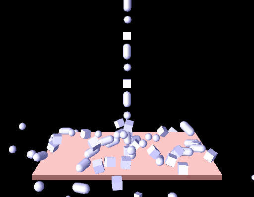
There are several bodies (slightly blue) falling onto a little floor object (a flat box, slightly red) - calculated by Tokamak.
If you want to compile the Visual Studio 7 project, you need two libraries:
If you do not have Visual Studio 7, you can either download the free "Express" edition or
build the files in your favorite IDE, that should not be too hard!
The components of the project
So you have seen the program running and have compiled it succesfully - now let's look at its parts.
If you are not familiar with tokamak, please read Adam Dawes' tutorials on Tokamak at
http://www.adamdawes.com, then proceed.
He has done a very good job on explaining Tokamak from the ground on.
The files
- camera.cpp
- spstructs.cpp
- spmath.cpp
(and the corresponding header files) are required for the camera, which is used in all my tokamak tutorials - see
my OpenGL page for further information.
I have written the files
as a little contribution to the tokamak community. The TokSim.cpp file contains the OpenGL display class, the TokSpring.cpp a
spring class. The first class will be explained later in the document, the second class in my third tutorial.
These 5 files mentioned above are the same in all my tutorials. Also, the main file SimpleSample.cpp (see below) is very similar
in all tutorials. In order to create your own Tokamak simulation, you only need a class, inherited from CTokSim, which
creates the simulation. In this tutorial this is done in SimpleTokSim.cpp.
Here is a more detailed explanation of these files:
-
SimpleSample.cpp
This is the main file with the "_tmain()" function - the entry point of the application.
Most of its content should be well known to you if you have read my OpenGL tutorials.
You should note line 45,
SimpleTokSim TokSim;
line 204,
TokSim.Init();
and the lines 91-94:
	//update the tokamak simulation:
	TokSim.CalculateNextFrame(0.02f);  //I use a fix time step (1/50 sec) for the examples

	//Call the display function of the tokamak-simulation class:
	TokSim.Display();
These lines form all the code related with the Tokamak simulation in the main file. They declare a variable of the class
SimpleTokSim which is inherited from the display class CTokSim, initialize it, let it proceed the simulation and
then display the scene.
-
SimpleTokSim.cpp
This is the file which defines the physics simulation. It contains the member functions of the class SimpleTokSim
(inherited from CTokSim, see SimpleTokSim.h for more information about this class).
As you can see, only the function "Init()" contains interesting code:
    neGeometry *geom;
    neV3 boxSize1;
    neV3 gravity;
    neV3 pos;
    gravity.Set(0.0f, -10.0f, 0.0f);

    //Init the simulation:
    CTokSim::Init(100,2,gravity);

    //Create rigid bodies. use boxes, spheres, and cylinders:
    for (int i=0; i<m_MaxRigidCount; i++)
    {
        // Create a rigid body using the CTokSim class:
        neRigidBody * rigid = CreateRigidBody();

        rigid->SetMass(0.01f);

        // Add geometry to the body and set it to be a box of dimensions 1, 1, 1
        geom = rigid->AddGeometry();
        boxSize1.Set(1.0f, 1.0f, 1.0f);
		if (i%3 == 0)
		{
			geom->SetBoxSize(boxSize1[0], boxSize1[1], boxSize1[2]);
			rigid->SetInertiaTensor(neBoxInertiaTensor(boxSize1[0], boxSize1[1], boxSize1[2],rigid->GetMass()));
		}
		if (i%3 == 1)
		{
			geom->SetSphereDiameter(1.0f);
			rigid->SetInertiaTensor(neSphereInertiaTensor(1.0f,rigid->GetMass()));
		}
		if (i%3 == 2)
		{
			static float Height = 1.0f;
			static float Diameter = 1.0f;
			geom->SetCylinder(Diameter,Height);
			rigid->SetInertiaTensor(neCylinderInertiaTensor(Diameter,Height,rigid->GetMass()));
		}

        // Update the bounding info of the object -- must always call this
        // after changing a body's geometry.
        rigid->UpdateBoundingInfo();


        // Vary the position so the cubes don't all exactly stack on top of each other
        pos.Set((float)(rand()%10) / 100, 4.0f + i*2.0f, (float)(rand()%10) / 100);
        rigid->SetPos(pos);
    }

    // Create an animated body for the floor
    neAnimatedBody * animated =  CreateAnimatedBody();
    geom = animated->AddGeometry();
    boxSize1.Set(FLOORSIZE, 0.5f, FLOORSIZE);
    geom->SetBoxSize(boxSize1[0],boxSize1[1],boxSize1[2]);
    animated->UpdateBoundingInfo();
    pos.Set(0.0f, -6.0f, 0.0f);
    animated->SetPos(pos);
Note the line
CTokSim::Init(100,2,gravity);
Here we initialize the tokamak simulation with 100 rigid and 2 animated bodies. Then you can see the code for a very
simple physical simulation, similar to Adam Dawes Tutorial 2 (indeed, its code is partly copied). But I do not create only
boxes but also sphere and cylinders.
The important thing is, that you absolutely do not have to care about storing information about the created objects in
order to display them later. The CTokSim class does this for you.
The display results
You may have wondered, why the little bodies falling down are displayed slightly blue and the floor is slightly red, although
you have not provided any display information.
The reason is simple: The class CTokSim displays rigid bodies slightly blue, animated bodies slightly red. This is helpful to
get a faster overview about the scene. You cannot change these settings (without editing the CTokSim.cpp file). This class
is not thought to produce good-looking results! It only displays the Tokamak simulation!
How does CTokSim work?
As explained above CTokSim is a base class for Tokamak simulations. It helps to seperate the simulation from the displaying
code.
My target was, that the user (you or me) does not have to care about displaying in any way. This is the reason why I decided
to put the Tokamak simulation and pointers to all rigid and animated bodies as protected member variables into the base class.
So the Display() function of CTokSim has access to the bodies and you do not have to add each body to the class.
If you look at the public member functions of CTokSim, you can see
- a constructor and a destructor
- an Init() method
- a Display() method
- methods to creates bodies or springs
- a method to return a pointer to the tokamak simulator object
- a method to proceed in the simulation ("CalculateNextFrame()")
The constructor only initializes some basic values but not the simulation itsself. The destructor destroys the simulation, if
it has been created before.
The Init() method initializes the tokamak simulator with numbers for the rigid and animated body counts. This method must be
seen as a little helper function. You might do this as well on your own, but the code is often the same, so I added this method.
After initializing the tokamak simulation, you can add bodies. Again, I have created some little helping functions for this.
The code is what you would expect it to be. As an example - here is the code of CreateRigidBody():
	neRigidBody * CTokSim::CreateRigidBody()
	{
	         if (m_RigidCount>= MAX_RIGID_COUNT)
	                 return NULL;

	         neRigidBody * rigid = m_Sim->CreateRigidBody();
	         m_Rigid[m_RigidCount++] = rigid;
	         return rigid;
	}
The heart of CTokSim is its Display() function. It works in four steps:
- draw the mesh
- draw the rigid bodies
- draw the animated bodies
- draw the springs
I have decided to use a very simple method to draw the mesh: Just render it solid and as wireframe, both without lighting.
Lighting would mean that you have to calculate normal vectors for each vertex of the mesh which means some effort. Because I
didn't find a method to query the mesh from Tokamak, I have added the method "SetTerrainMesh(...)". You have to use this method
if you want CTokSim to display the mesh. It copies the vertices and indices to an OpenGL vertex array.
To display the rigid and the animated bodies is more or less the same:
- Apply the transformation matrix of the body
- iterate over all geometries of the body:
- Apply the transformation matrix of the geometry "within the body's coordinate system"
- display the geometry
Displaying boxes and spheres is quite simple if you query their size. The tokamak cylinders, which are capsules, can be displayed
by drawing a "real" cylinder and adding two half spheres on the top and on the bottom. I draw simply complete spheres as the other
half disappears within the cylinder.
The detail level of the spheres and cylinder is defined in line 11 of TokSim.cpp. The higher this value is set, the more
polygons are used to render the spheres and cylinders. I have chosen quite a low level - which is faster and helps you to see,
if the bodies are rotating (you cannot see this at a lit, one-colored, "perfect" sphere!).
Springs are displayed as simple lines between their connection points. The color is dependent from their length. More about springs
in the Spring tutorial.
**************************************************************************
>>> continue to the joint tutorial
**************************************************************************
Any comments? Conact me!
philipp.crocoll@web.de
www.codecolony.de