In order to learn how the two different joint types work, let's create a simple scene with both types.
First, the hinge joint: Imagine two flat boxes, placed next to each other and connected with each other at the touching edge.
The following code creates these boxes:
	//Create two flat boxes next to each other:
	neRigidBody * box1 = CreateRigidBody();
	geom = box1->AddGeometry();
	geom->SetBoxSize(10.0f,1.0f,10.0f);
	box1->UpdateBoundingInfo();
	box1->SetMass(0.05f);
	pos.Set(0.0f,15.0f,0.0f);
	box1->SetPos(pos);

	neRigidBody * box2 = CreateRigidBody();
	geom = box2->AddGeometry();
	geom->SetBoxSize(10.0f,1.0f,10.0f);
	box2->UpdateBoundingInfo();
	box2->SetMass(0.05f);
	pos.Set(0.0f,15.0f,10.0f);
	box2->SetPos(pos);
If they fall down, nothing interesting will happen, because there is no real torque on one of them. So let's create a cylinder
with which the boxes will collide:
	//create another animated (=fixed) object - a cylinder which will be placed standing on the floor:
	neAnimatedBody * animCyl = CreateAnimatedBody();
	geom = animCyl->AddGeometry();
	geom->SetCylinder(10.0f,5.0f);
	pos.Set(0.0f,0.0f,3.0f);
	animCyl->SetPos(pos);
	animCyl->UpdateBoundingInfo();
Now comes the joint. The code is as follows:
	//Create a joint (hinge) between these two boxes:
	neJoint * joint;
	joint = m_Sim->CreateJoint(box1,box2);

	neT3 trans;
	trans.pos.Set(0.0f,15.0f,5.0f);;
	trans.rot[0].Set(0.0f, 0.0f, 1.0f);
	trans.rot[1].Set(1.0f, 0.0f, 0.0f);
	trans.rot[2].Set(0.0f, 1.0f, 0.0f);
	joint->SetJointFrameWorld(trans);

	joint->SetType(neJoint::NE_JOINT_HINGE);
	joint->SetLowerLimit(-NE_PI*0.9f);
	joint->SetUpperLimit(NE_PI*0.9f);
	joint->EnableLimit(true);
	joint->SetJointLength(10.0f);

	joint->Enable(true);
At first, a joint is created using the m_Sim member variable of the base class. This is the Tokamak simulator. As parameters
we pass the two bodies we want to connect.
The next lines seem to be a bit weird - but they are not. The last line of this block (joint->SetJointFrameWorld(trans);)
sets the so called joint frame. The suffix "World" means that this is done in world coordinates. You also have the possibility
to use the coordinate system of body1 or body2 - use SetJointFrameA/B() then. The frame contains the information about where
the joint is created (we wouldn't have to create it at the edge where the body touch each other - we could choose another axis)
and - only for hinge joints - the direction of the joint axis.
So the position is simple - the point in the middle of the joint axis is (0,15,5), so this is trans.pos.
What about the rotation? Our joint shall be parallel to the x-axis. In identity matrix would mean that it is parallel to the
y-axis. The rotation matrix above maps the vector (0,1,0) (y-direction) to (1,0,0) (x-direction) - it is a simple rotation matrix.
Now it gets easier again: the next line sets the joint type NE_JOINT_HINGE. Then there are three lines which set and enable the
joint limit. What is this? As I mentioned in the introduction you can turn your hand only within certain limits (otherwise
you should maybe visit your doctor :-)). So this is the case not only in ball and socket joints but also in hinge joints.
You can define a lower and an upper limit. The angle (radian) between the two bodies will always stay between these two limits.
Our two boxes shall have quite a big angle interval. They may rotate 90% of a half rotation in each direction. If you would set the limits
to -PI and +PI, they would seem not to collide. Indeed - they do not collide, which is intended. Otherwise they could not even rotate
a little bit around the joint axis, because they would collide at once. (Note that the CollideConnected value does not have to do anything with this.
See the Sample 1 short explanation).
As we have set the position and direction of the joint (using SetJointFrameWorld), we also should set the length of the joint.
If we imagine the boxes to be completedly connected, we set this to the length of the edge (10.0f).
The last line is probably the most important one: you always have to enable the joint, otherwise it will have no effect!
That's all you need to create a hinge joint!
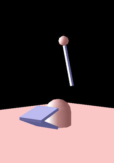
So let's look at a ball and socket joint. Imagine a sphere "hanging in the air" - an animated object. Let's add a box which touches
this sphere. If you use a ball and socket joint - this touch will always stay.
This is the code to create the two bodies: (note: Here we have animated/rigid combination, but this does not have an effect
on the joint):
	//create a fixed sphere "hanging in the air"
	neAnimatedBody * animSphere = CreateAnimatedBody();
	geom = animSphere->AddGeometry();
	geom->SetSphereDiameter(4.0f);
	animSphere->UpdateBoundingInfo();
	pos.Set(0.0f,30.0f,0.0f);
	animSphere->SetPos(pos);


	//Create a box "hanging" on the animated sphere
	neRigidBody * rigidSphere = CreateRigidBody();
	geom = rigidSphere->AddGeometry();
	geom->SetBoxSize(16.0f,1.0f,1.0f);
	rigidSphere->UpdateBoundingInfo();
	pos.Set(10.0f,30.0f,0.0f);
	rigidSphere->SetPos(pos);
There is no surprise about this code, I suppose. So let's look at the joint:
	//Create the joint (ball and socket) between the spheres:
	joint = m_Sim->CreateJoint(rigidSphere,animSphere);
	trans.pos.Set(animSphere->GetPos());
	trans.rot.SetIdentity();
	joint->SetJointFrameWorld(trans);
	joint->SetType(neJoint::NE_JOINT_BALLSOCKET);
	joint->SetDampingFactor(20.0f);

	joint->Enable(true);
Looks very like the code for the hinge, doesn't it? It's even easier: The joint is created with the same call to
CreateJoint(), then we set the joint frame - the rotation matrix doesn't matter for ball and socket joints. So set it to
identity. As position we set the center of the sphere! If we would set the touching point, the box would rotate arount this
point on the surface of the sphere.
Then we set the type of NE_JOINT_BALLSOCKET.
You can also add a limit for ball and socket joints, but instead, I want to introduce the joint damping. It's easy to understand -
the higher this factor, the stronger the damping. It looks a bit strange, that the box doesn't stop moving when it is hanging
exactly under the sphere in our case here, but this is one result of the damping - I have not found a way to solve this.
Please consider that you see the box only rotating around the z-axis. If you would apply impuls to it in z-direction you will
see that this is really a ballsocket!
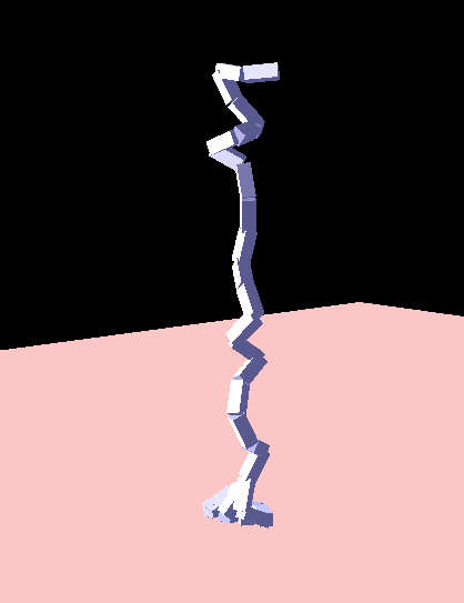
Providing this file I wanted to show how simple it is to compile Tokamak's samples using my CTokSim class.
I changed the input handling a bit (which is very rudimentary in my sample). You lift the chain with "i". ("q" is already
in use for the camera.)
If you have read the paragraph above, you shouldn't have problems understanding the sample 1 code anymore:
It creates several boxes and connects them with ball and socket joints.
Here the call to CollideConnected() might be new to you. It is often thought this function must be called, if two bodies which
are connected via a joint, fall into each other. This is
not the case. You can only use the joint limits to achieve this!
This function gets useful if you connect more than two bodies! This can be seen well in this sample:
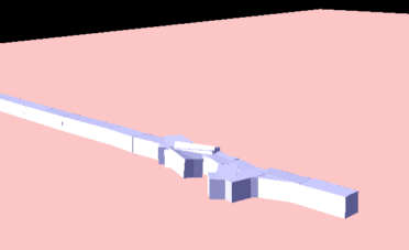
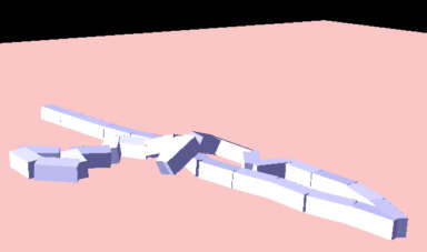
The first image has been created with CollideConnected(false), the second with CollideConnected(true). In the first one the
boxes didn't collide correctly - in the second, they did!
The lines
		lastJoint->SetEpsilon(EPSILON);

		lastJoint->SetIteration(5);
set the accuracy of the joint.